- 您现在的位置:买卖IC网 > Sheet目录310 > AP8802SPG-13 (Diodes Inc)IC LED DRIVER HIGH BRIGHT 8SOIC
AP8802
1A LED STEP-DOWN CONVERTER
Application Information
LED Current Control
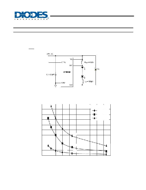
The LED current is controlled by the resistor R SET in Figure 14 connected between V IN and SET. The nominal average output current in the
LED(s) with the CTRL pin open circuit is defined as:
I LED =
V THD
R SET
where V THD is the voltage between the V IN and SET pins and is nominally 200mV.
Figure. 14 Typical Application Circuit for I LED = 1A
Inductor Selection
This section highlights how to select the inductor suitable for the application requirements in terms of switching frequency, LED current
accuracy and temperature.
500
450
400
68
Switching Frequency @ I LED = 700mA
12V - 3 LEDs
24V - 5 LEDs
350
47
100
48V - 10 LEDs
300
250
200
68
100
150
220
150
150
100
47
68
220
470
50
100
150
220
470
0
470
0
50
100
150
200
250
300
350
400
450
500
INDUCTOR VALUE (μH)
Figure. 15 Switching Frequency vs. Inductor Value
The inductor influences the LED current accuracy that the system is able to provide. The following section highlights how to select the
inductor in relation to the device packages and the LED current, while maintaining the chip temperature below 70°C.
AP8802
Document number: DS31766 Rev. 9 - 2
7 of 19
www.diodes.com
May 2012
? Diodes Incorporated
发布紧急采购,3分钟左右您将得到回复。
相关PDF资料
AP8803WTG-7
IC LED DRIVER CONN CURR TSOT23-5
APEK4402KLP-01-T-DK
BOARD EVAL FOR A4402
APP-001-15AMP
PLUG AUTO PWR BLACK W/LED 15AMP
APP-001-20AMP
AUTO PLUG 12VOLT WITH 20AMP FUSE
APP-001-VO
PLUG AUTO PWR BLACK W/LED IND
APP-001
PLUG AUTO PWR BLACK W/LED IND
APP-002
PLUG AUTO PWR GRAY W/LED IND
APP-003
PLUG AUTO PWR BLACK W/O LED IND
相关代理商/技术参数
AP8803
制造商:DIODES 制造商全称:Diodes Incorporated 功能描述:Cost effective 3W LED driver for consumer applications
AP8803EV1
功能描述:AP8803 1, Non-Isolated Output LED Driver Evaluation Board 制造商:diodes incorporated 系列:- 零件状态:有效 电流 - 输出/通道:680mA 输出和类型:1,非隔离 电压 - 输出:- 特性:可调光 电压 - 输入:8 V ~ 30 V 所含物品:板 使用的 IC/零件:AP8803 标准包装:1
AP8803WTG-7
功能描述:LED照明驱动器 BUCK LED DRIVER 30V 3W RoHS:否 制造商:STMicroelectronics 输入电压:11.5 V to 23 V 工作频率: 最大电源电流:1.7 mA 输出电流: 最大工作温度: 安装风格:SMD/SMT 封装 / 箱体:SO-16N
AP8821
制造商:APLUS 制造商全称:APLUS 功能描述:21 sec VOICE OTP
AP8841
制造商:American Power Conversion Corp (APC by Schneider Electric) 功能描述:RACK PDU 2G, METERED, ZEROU, 30A, 200/208V, (36) C13 & (6) C19 制造商:Schneider Electric 功能描述:RACK PDU 2G, METERED, ZEROU, 30A 200/208V, (36) C13 & (6) C1 - Bulk
AP8842
制造商:APLUS 制造商全称:APLUS 功能描述:42 sec VOICE OTP
AP8853
制造商:Schneider Electric 功能描述:RACK PDU 2G, METERED, ZEROU, 32A, 230V, (36) C13 & (6) C19 - Bulk
AP8853-25PI
制造商:ANSC 功能描述:AP8853-25PI 300MA 2.5V LDO LINEAR REGULATOR /OGI
